
As part of a project, I needed to study signals sent out by IR remote control units that control TVs, Receivers, etc. The signal itself will be captured using a USB Logic Analyser. But how do I get the signal itself? There are two ways to do this. Use a simple photo-transistor to sense the IR output or directly measure the signal going to the IR LED inside the remote. I decided to use the second approach.
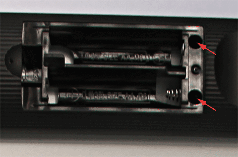
The remote control unit is a Sony RM-AAP050 and it controls a Sony STR-DH810 receiver. The first step was to pull the IR remote apart to get at the IR LED. You start with unscrewing the two small philips screws just above the battery compartment.
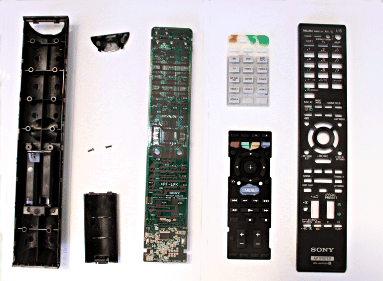
Once the screws are removed, the two halves of the case can be prised apart. The various parts are laid out below.
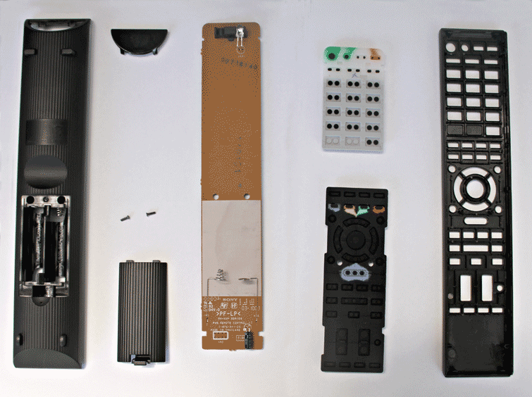
Here is the underside of the parts. Near the top edge of the PCB is the IR LED.
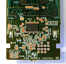
Here is a closup of the chip. It is an NEC D197F114. I could not track down the datasheet on the web.
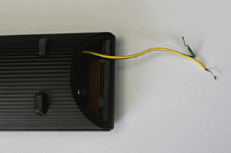
Once the case is opened, you can solder a couple of wires to the IR LED. When I assembled the remote unit back, I left out the grey filter in front of the IR LED so that I can get the wires out.
Now I am ready to study the signals and I will describe it in a future post.
No comments:
Post a Comment