
In the previous blog, I connected two wires to the IR LED of a Sony IR remote control. Now it is time to study the IR signal format. I hooked it up to a USB Logic Analyser. The signal looks like this.
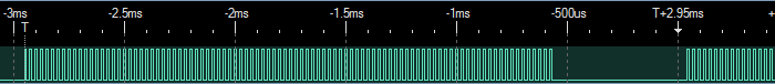
The signal consists of bursts of a carrier signal and idle periods. Let us look closely at the carrier signal.
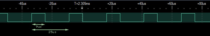
The period of the carrier signal is 25 us. The on period of the signal is 9us. This works out to a carrier frequency of 40 KHz with a 36% duty cycle. Now let us look at the signal as a whole.
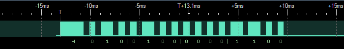
As a convention, let us call the presence of the carrier signal as a mark and the idle portion as a space. The signal has a header which consists of a mark of 2400 us and a space of 600 us. This is followed by the data. The space is always 600 us and the mark has two values 1200 us and 600 us. This is the data portion. Each mark and space represents one bit of data. Let the longer mark represent a one and the shorter mark a zero. There are 15 bits of data. The data represented by the above signal is 010 0100 0000 1100 or 240C in hex.
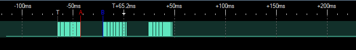
Looking at a longer duration, you can see that the signal is sent multiple times. The gap between each burst is the same - about 22 ms. The signal is sent 3 times.
In the Sony signal format, the length of the mark indicates the bit value. This is called Pulse Encoding. Here is a pulse train from a JVC remote. Here the mark portion of the signal is the same and the bits are encoded by varying the space portion. This is called Space Encoding.
The signal has a header which consists of a mark of 8800 us and a space of 4000 us. This is followed by the data. The mark is always 750 us. The space has two values 1350 us and 300 us. Let the longer space represent a one and the shorter space, a zero. The above signal has 16 bits of data. As the space period is significant, the last space is followed by a mark and then the gap. This last mark indicates the end of the signal and is not included in the data. The binary representation is 1100 0010 0011 0000 or C230 in hex.
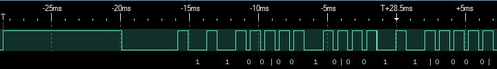
The third encoding is Phase Encoding. I don't have an actual example but the signal looks like the one below.

There is the usual header mark and space. This is followed by slots of equal width. Let the case where the slot starts with a space and then transitions to a mark be a zero and the opposite be a one. The data above has 8 bits and the binary representation is 1011 0111 or B7 in hex.
Coding Scheme
The remote control signal for most remote controls have their own Coding Schemes. They have the following characteristics.
- Wavelength of light (in the IR region and not measured here)
- Carrier Frequency
- Carrier Duty Cycle
- Encoding (Pulse, Space or Phase Encoding)
- Number of bits
- Mark duration for header
- Space duration for header
- Mark duration for a one
- Space duration for a one
- Mark duration for a zero
- Space duration for a zero
- No. of repetitions
- Gap between each repetition
The above characteristics completely describe the signals from Sony and JVC remote controls. The values can be summarised as below
| Manuf. | Carrier Freq. (KHz) |
Duty Cycle (%) |
Encoding | Data Bits |
Header Pulse (us) |
Header Space (us) |
One Pulse (us) |
One Space (us) |
Zero Pulse (us) |
Zero Space (us) |
No. of Reps |
Gap for Reps (ms) |
|---|---|---|---|---|---|---|---|---|---|---|---|---|
| Sony | 40 | 36 | Pulse | 12/15 | 2200 | 550 | 1100 | 550 | 550 | 550 | 3 | 22 |
| JVC | ? | ? | Space | 16 | 8800 | 4000 | 750 | 1350 | 750 | 300 | ? | ? |
One of the remote controls I have is for a Foxtel IQ set-top box. The signal from this IR remote does not fall into the above formats. We will look at this in the next blog.
No comments:
Post a Comment